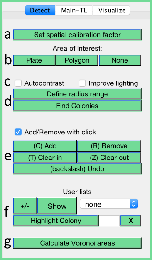
We will refer to the letters on the image below for the following instructions:
GUI overview (modified Fig S1 from manuscript)
Spatial calibration (a)
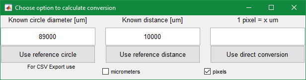
Three options to define a pixel to micrometer spatial calibration factor are available:
Set spatial calibration (a)
Enter the known diameter of a circle (e.g. 89’000 micrometers for the inner circle of a standard agar plate) in the editable field and click the Use reference circle button below. A proposed circle is automatically detected and displayed. Either confirm this circle or alter it by clicking on three points on the circle which you want to utilize.
Enter any known distance in the editable field and click the Use reference distance button. A ruler will be displayed on the image. The ruler should be scaled and moved appropriately and confirmed by hitting enter.
Directly enter the known spatial calibration factor and confirm with the button Use direct conversion.
Also note that one can switch the default exporting unit from pixels to micrometers in here.
In EP mode, the spatial calibration factor is only applied to the current frame. Propagate it from the current frame to all frames with Options/Main-EP/Apply calibration factor to all frames.
Area of interest (b)
Automatic colony detection can be narrowed to the defined boundaries of an area of interest (AOI). Users can select the plate as AOI or draw a custom polygon on the image. Using an AOI is suggested to reduce computational time and reduce false positive detection outside the boundaries of e.g. an agar plate. The AOI is displayed as a blue circle or polygon depending on the chosen option.
In EP mode, the spatial calibration factor is only applied to the current frame. Propagate it from the current frame to all frames with Options/Main-EP/Apply AOI to all frames.